
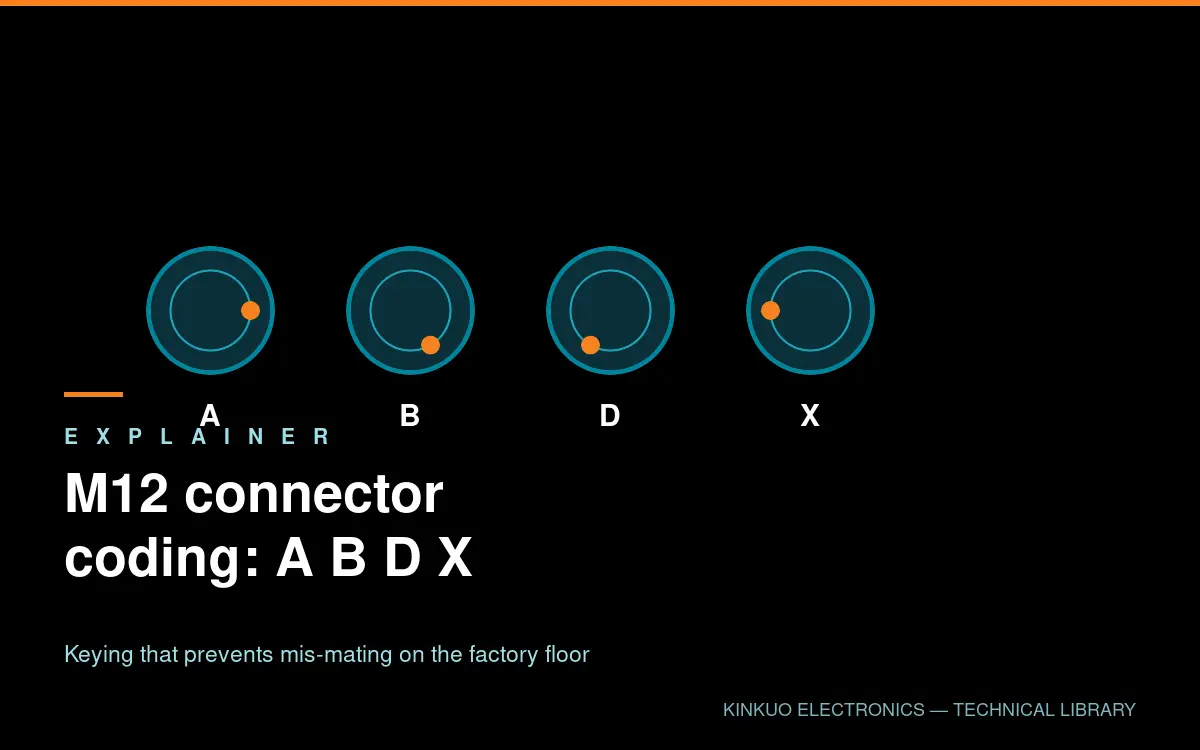
The M12 connector is one of the few industrial interfaces adopted almost universally, across vendors and protocols. A large part of that success comes from coding — the mechanical keying that prevents a sensor cable being plugged into an Ethernet port.
Four coding variants account for most installations.
M12 connector coding: A-coded, the original sensor interface
A-coding is the original M12 layout, most commonly in 3, 4, 5 and 8-pin versions. It carries DC power and discrete or analogue signals, and it is what you will find on proximity sensors, photoelectric sensors, small actuators and valve manifolds.
The 4 and 5-pin versions are the workhorses. A 5-pin A-coded connector typically carries 24 V supply plus two signal conductors, with the fifth position either spare or used for a second output.
Because A-coding is the default, it is also the code that gets plugged into the wrong thing most often. That is precisely why the other codings exist.
B-coded: fieldbus and legacy networks
B-coding was developed for early fieldbus systems, notably PROFIBUS and Interbus. It uses a different keyway and a two-pair layout. It is now largely a legacy format — new installations generally use D-coded for industrial Ethernet — but plenty of B-coded equipment remains in service, and maintaining it depends on the parts still being available.
D-coded: Industrial Ethernet at 100 Mbit/s
D-coding was designed specifically for Industrial Ethernet: PROFINET, EtherNet/IP and EtherCAT at 100 Mbit/s. It provides four contacts arranged as two differential pairs, with the keyway positioned so it cannot mate with an A-coded sensor connector.
The 100 Mbit/s limitation is a function of the contact arrangement and the cable specified for it, not a hard ceiling on the connector itself. For most machine-level Ethernet — drives, remote I/O, HMI panels — 100 Mbit/s is more than sufficient, and D-coded remains the standard choice.
X-coded: 10 Gbit/s in a rugged shell
X-coding brings Cat.6A performance — 10 Gbit/s — into the M12 form factor. It uses eight contacts arranged as four shielded pairs, with a cross-shaped keyway that is unmistakable both visually and by touch.
X-coded M12 is the standard interface for GigE Vision cameras with 10G capability, high-resolution machine-vision controllers, and rugged edge computing where an RJ45 would not survive. The shielding strategy is the critical detail: each pair is individually shielded within an overall braid, and the whole assembly must maintain Cat.6A performance through the connector and the cable strain relief.
M12 connector coding is not just about pin count
Two connectors with the same number of contacts and the same thread can be completely incompatible if the coding differs. More importantly, coding is a safety mechanism: it makes an incorrect connection physically impossible rather than merely unlikely.
On a machine with dozens of M12 ports, a mis-plugged cable can destroy a sensor, a drive input or a camera. Coding is a cheap, permanent safeguard against that class of error.
Specifying M12 connectors
When ordering, state the coding, the pin count, the gender, the mounting style and the protection rating. For field-wireable parts, also confirm the cable entry diameter and conductor cross-section.
Our M8, M12, M16 and M23 connector range covers A, D and X coding in male and female, field-wireable and PCB-mount styles. For camera installations, the corresponding RJ45-to-M12 camera cables are built with Cat.6A construction and IP67 sealing. If you are unsure which coding your equipment uses, send us a photograph of the port and we will identify it.
Standards and further reading
Primary reference material for this topic is published by EMVA standards, PROFIBUS & PROFINET International, A3 Vision Standards. Where a customer programme requires conformance to a specific standard, tell us at the enquiry stage and we will confirm what documentation we can supply.
Leave a Reply