
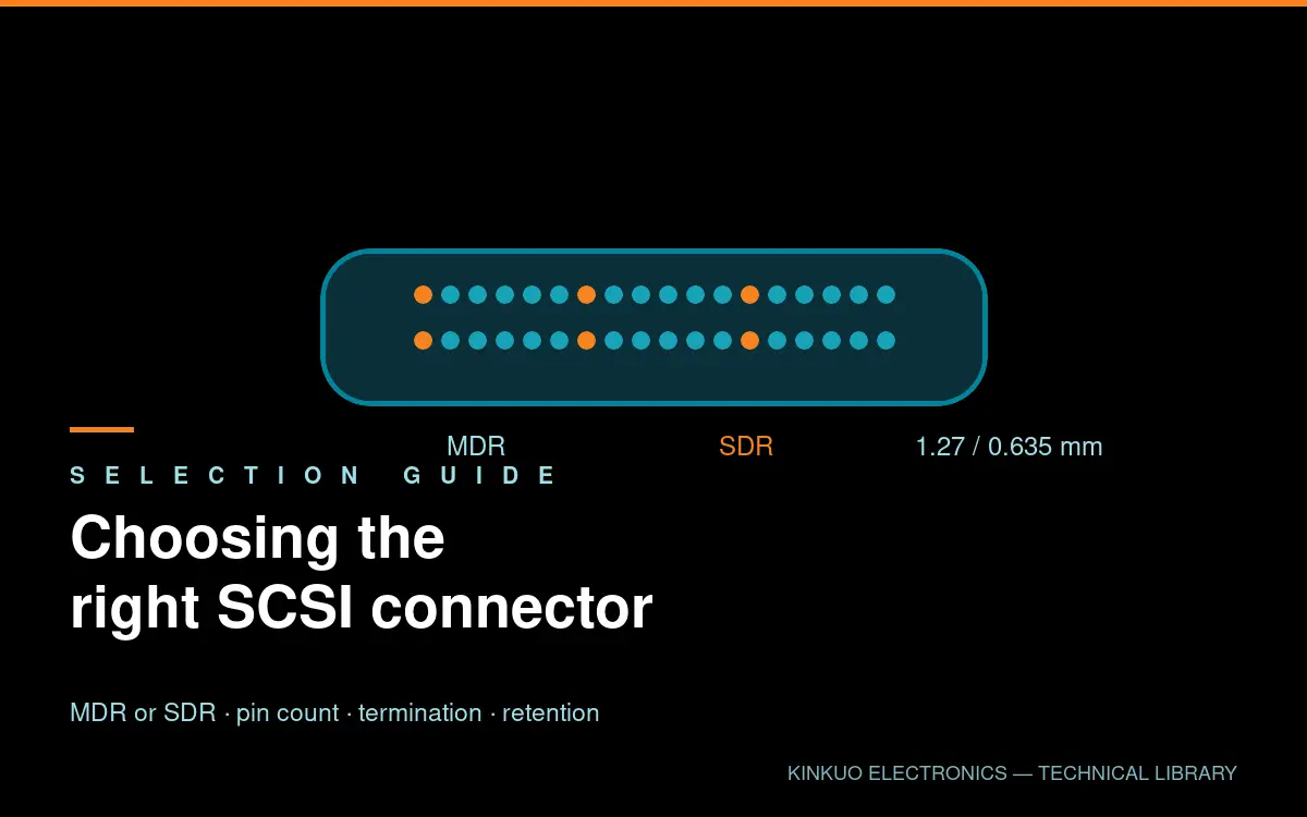
SCSI connector designs have outlived the storage standard that gave them their name. Today they carry industrial camera links, motion-controller I/O and laboratory instrumentation — and choosing between the available variants comes down to four decisions.
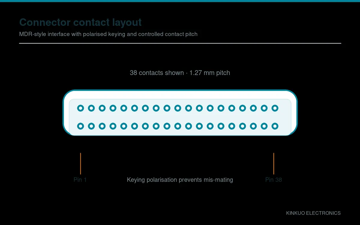
Choosing between the available variants comes down to four decisions: family, pin count, termination style and shell retention.
SCSI connector families: MDR or SDR?
The Mini D Ribbon (MDR) family uses a 1.27 mm contact pitch in a shell that accepts either a screw-lock or a spring-latch retention mechanism. It is the more common choice for industrial cabling because the connectors are widely available, tooling is mature, and the mechanical design tolerates repeated mating.
The Shrunken D Ribbon (SDR) family halves the pitch to 0.635 mm, which roughly doubles the contact density in a similar footprint. SDR parts are used where board space is at a premium, and the shielded versions are common on Camera Link frame grabbers because the tighter geometry shortens the electrical path from the connector to the differential pairs.
If you are maintaining existing equipment, the family is already decided — match what is there. If you are designing new, MDR generally offers more headroom on assembly and serviceability.
Pin count
Pin count is usually set by the interface rather than by preference. Common configurations and their typical uses:
- 14, 20 and 26 pin — breakout applications, analogue video and compact multi-signal runs
- 36 pin — the standard Camera Link interface and a common motion-controller I/O format
- 40, 50 pin — higher channel counts on controllers that need more I/O per connector
- 68 pin — SCSI-II legacy control interfaces, still widespread in servo drives and lab equipment
- 100 pin — high channel counts on data-acquisition and legacy storage systems
Where an interface is already defined, use the specified count. Where it is not, leave spare positions: filling a connector to capacity leaves no headroom for a later revision.
Solder, crimp or IDC termination
Solder-cup termination is the default for low and medium volumes because it needs no dedicated tooling and is straightforward to repair in the field. It does, however, place the skill of the assembler directly into the electrical performance.
Crimp termination gives more consistent results at volume — the tooling controls the joint rather than the operator — but requires the right crimp frame and die set.
IDC, or insulation-displacement, termination suits flat ribbon cable where the geometry is fixed and volume is high. It is fast, but it does not flex well, so it is a poor fit for moving applications.
Hood and retention
The hood is more than a cosmetic part. On a cable assembly it carries the strain relief, provides the shield termination and determines how the connector is retained.
Screw-lock retention is the right choice where a cable is mated once and left in place — it will not release under vibration. Spring-latch retention suits applications where a cable is connected and disconnected regularly during setup or maintenance, because it releases one-handed.
Material matters too. A die-cast zinc hood gives real shielding mass for high-speed or noisy environments, while an ABS hood is lighter and lower cost for general signal cabling. Where a link runs beside drive cabling, the zinc hood is usually worth the small additional cost.
Matching the cable to the connector
The connector is only half the assembly. For differential signalling, the cable must be constructed as twisted pairs with individual shielding where the link is long or electrically noisy, and the overall shield must be terminated to the connector shell rather than left floating.
This is the single most common cause of intermittent Camera Link and LVDS faults: a cable that looks correct but whose shield stops short of the shell, leaving the pairs exposed to whatever the cabinet is radiating.
Getting it right the first time
If you have a part number, a drawing or a photograph of a failed connector, our engineering team can cross-reference it and confirm the equivalent along with any differences in construction. If you are designing new, tell us the interface, channel count, environment and volume and we will recommend a configuration.
Browse the SCSI connector range, view SCSI cable assemblies, or contact our engineering team for a cross reference.
Standards and further reading
Primary reference material for this topic is published by INCITS T10, EMVA standards, IEC. Where a customer programme requires conformance to a specific standard, tell us at the enquiry stage and we will confirm what documentation we can supply.
Leave a Reply