
An encoder alarm sends maintenance teams to the drive, the motor and the controller. In a significant proportion of cases the actual cause is the servo encoder cable between them.
Servo encoder cable fault one: incorrect pair assignment
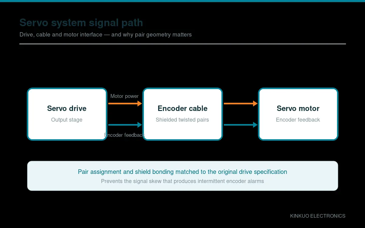
Encoder signals are differential. The A+, A−, B+, B−, Z+ and Z− pairs each need to travel together as a twisted pair with consistent impedance. A replacement cable that uses a different pair assignment, or that separates the members of a differential pair, will produce signal skew that the drive interprets as position error.
This is the most common failure introduced by sourcing a replacement on price alone. The cable looks identical, fits perfectly, and produces intermittent alarms that appear to worsen with speed.
The fix is straightforward: match the pair assignment of the original. This is why our servo cables are cross-referenced to the OEM part numbers — the pair geometry is part of the specification, not a manufacturing preference.
Failure mode two: incomplete shield bonding
Encoder signals are low voltage and high impedance, which makes them sensitive to electromagnetic interference. If the cable shield is bonded at only one end, or not bonded at all, the pairs act as an antenna for whatever the drive cabinet is radiating.
Correct practice is to bond the shield to the connector shell at both ends, with a 360° termination rather than a drain wire. Where a driven shield is used, the drive’s instructions take precedence.
Failure mode three: flex fatigue
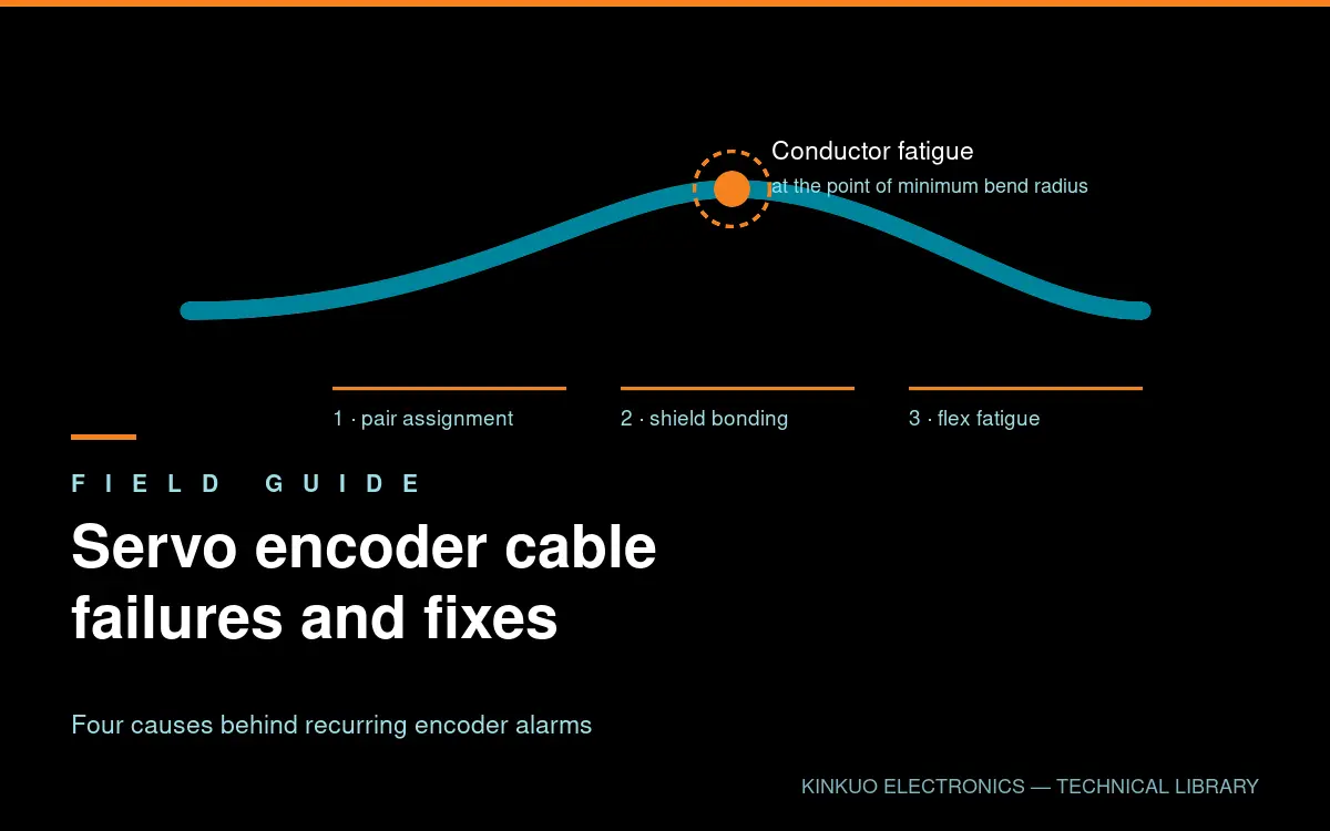
Encoder cables on moving axes are subject to continuous bending. A cable designed for static installation will fail, typically at the point of minimum bend radius, and the failure will be mechanical — fractured conductors — rather than electrical.
The symptoms of flex fatigue differ from interference: the fault appears at a specific position of the axis rather than randomly, and it becomes more frequent over time as more strands break.
Drag-chain rated encoder cables use finely stranded conductors, fillers that maintain internal geometry and a jacket formulated for continuous flex. Specifying them costs a little more and removes an entire failure category.
Failure mode four: connector and strain relief damage
The connector body is often the first casualty. Pulling a cable by its connector, forcing it around a tight corner at the cabinet entry, or omitting strain relief all transfer mechanical load into the termination, where it eventually breaks individual conductors.
Inspection of a failed cable usually shows the damage at the cabinet entry rather than at the motor, because that is where the bend is tightest and the strain relief is often missing.
Prevention: a short checklist
- Specify drag-chain rated cable for any moving axis, and state the bend radius
- Cross-reference the OEM part number rather than matching connectors visually
- Verify shield continuity end to end before commissioning
- Install proper strain relief at both ends and check the cabinet entry radius
- Route encoder cables separately from motor power cables wherever possible
- Keep spare cables on the shelf; a cable is a consumable on a high-cycle axis
Diagnosing an intermittent servo encoder cable fault
Start by substituting a known-good cable. If the fault disappears, stop investigating the drive — you have found it. If it persists with a new cable, the original may have been damaged by a mechanical problem, such as a misaligned cable carrier or a loose motor mount, that will damage the replacement in the same way.
If a cable has failed twice in the same location, the problem is almost certainly mechanical rather than electrical, and the routing needs to change rather than the cable specification.
Selection and cross-reference
Our servo motor and encoder cable range covers Siemens SINAMICS V90, Panasonic MINAS A5/A6, Mitsubishi MELSERVO and FANUC platforms, with pair assignment matched to the original designs and high-flex construction rated to 10 million bending cycles.
Send us the OEM part number and we will confirm the equivalent. Contact our engineering team or read more about our quality control and testing process.
Standards and further reading
Primary reference material for this topic is published by IEC. Where a customer programme requires conformance to a specific standard, tell us at the enquiry stage and we will confirm what documentation we can supply.
Leave a Reply