
Machine-vision faults are frequently blamed on the camera or the software when the real cause sits in the camera cable. Choosing the right construction removes an entire category of intermittent problems.
Camera cable selection: two interfaces, two failure modes
Camera Link uses the MDR 26-pin or 36-pin connector (and SDR 26-pin on some frame grabbers) to carry multiple LVDS differential pairs plus control signals. Because the data pairs run at high rates over a parallel interface, the cable is the dominant variable in link quality. Shield termination and pair geometry matter more than cable length within the rated limit.
GigE Vision uses standard Ethernet physical layers — RJ45 or M12 — and carries data over a serialised link with error correction. This is more forgiving of cable quality in principle, but the packet-based nature of the link means a marginal cable produces dropped frames rather than an obviously degraded image, which can be harder to diagnose.
Connector selection
For Camera Link, the 36-pin MDR is the common base configuration. Retention choice depends on how often the cable is mated: screw-lock for permanent installation, latch for cameras that are moved or serviced regularly. For high-noise environments, choose a die-cast zinc hood over ABS — the additional shielding mass makes a measurable difference when the cable runs alongside drive cabling.
For GigE Vision, the camera end is usually an M12. The coding matters: D-coded for 100 Mbit/s, X-coded for 10 Gbit/s. The cabinet end is typically RJ45. A cable that converts between them must maintain the performance of the more demanding end, which is why an X-coded 10G cable needs Cat.6A construction throughout, not just at the connector.
Shielding: where most problems originate
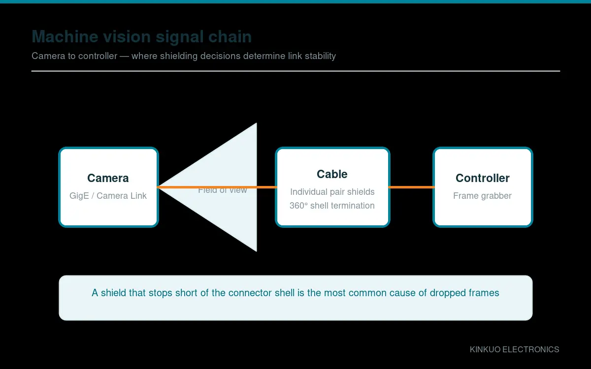
The most common defect we see in failed camera cables is a shield that stops short of the connector shell. It may be terminated to a drain wire, or folded back under a clamp, or simply left floating. In each case the differential pairs are exposed to whatever the cabinet is radiating.
Correct construction terminates the cable shield to the connector shell around the full circumference. On assemblies with individually shielded pairs, each pair’s shield is terminated as well. This is not a premium option — it is the baseline for a cable that has to carry high-rate differential signals.
Flex and routing
Cameras on moving axes need drag-chain rated cable. A general-purpose camera cable used in a carrier will fail within months, and the failure will appear as an intermittent frame drop that is maddening to diagnose because it only occurs at particular positions of the axis.
Route camera cables away from drive cables where possible. Where they must cross, cross at right angles rather than running parallel. Keep the bend radius generous and use proper strain relief at both the camera and cabinet ends.
Camera cable length limits
Camera Link has defined length limits that depend on the configuration and clock rate — exceeding them produces bit errors rather than a clean failure. GigE Vision is nominally 100 m on copper, but in electrically noisy environments the practical limit is shorter, and power over Ethernet adds its own constraints.
If you need more reach than the interface allows, the correct answer is a repeater or a fibre link, not a longer copper cable.
Diagnosing a suspected cable fault
- Swap the cable for a known-good one. If the fault moves, the cable is the cause.
- Flex the cable by hand along its length while watching the image or error counter. A change at a specific point localises the fault.
- Check the shield continuity from the connector shell to the far end with a multimeter.
- Inspect the cabinet entry, which is where most flex damage begins.
Specifying camera cables
Our industrial camera cable range covers RJ45-to-M12 in A, D and X coding, Cat.5e and Cat.6A GigE assemblies, and MDR-to-SDR Camera Link harnesses, all built with individually shielded pairs and 360° shield termination.
Tell us the camera model, interface, cable length, motion profile and environment, and we will recommend a construction. Contact our engineering team or browse MDR cable assemblies.
Standards and further reading
Primary reference material for this topic is published by REACH, EMVA standards, PROFIBUS & PROFINET International. Where a customer programme requires conformance to a specific standard, tell us at the enquiry stage and we will confirm what documentation we can supply.
Leave a Reply